
INTRODUCTION
Concrete masonry is used to construct various foundation wall types, including full basement walls, crawlspace walls, stem walls and piers. Concrete masonry is well suited for below grade applications, because of its strength, durability, economy, and resistance to fire, insects and noise. The modular nature of concrete masonry allows floor plan and wall height changes to be easily accommodated as well. Concrete masonry can be used to provide a strong, durable, energy efficient and insect resistant foundation for all building types.
This TEK contains details for various types of concrete masonry foundation walls, with accompanying text as appropriate. The reader is referred to TEK 03-11, Concrete Masonry Basement Wall Construction, TEK19-03B, Preventing Water Penetration in Below Grade Concrete Masonry Walls and CMHA’s Basement Manual for more detailed design and construction information (refs. 2, 3, 4, respectively).
Footings
Footings lie under the basement, crawlspace or stem wall and transfer structural loads from the building to the supporting soil. Footings are typically cast-in-place concrete, placed beneath the frost depth to prevent damage resulting from heaving caused by freezing of water in the soil.
Footings should be placed on undisturbed native soil, unless this soil is unsuitable, weak or soft. In this case, the soil should be removed and replaced with compacted soil, gravel or concrete. Similarly, tree roots, construction debris and ice should be removed prior to placing footings.
Unless otherwise required, footings should be carefully aligned so that the concrete masonry wall will be near the center line of the footing. Although the top surface of poured concrete footings should be relatively level, it should generally not be troweled smooth, as a slightly roughened surface enhances the bond between the mortar and concrete. Concrete footing design is governed by Building Code Requirements for Structural Concrete, ACI 318 (ref. 5), and concrete foundations are constructed with tolerances conforming to the requirements of Standard Specifications for Tolerances for Concrete Construction and Materials, ACI 117 (ref. 9).
BASEMENT WALLS
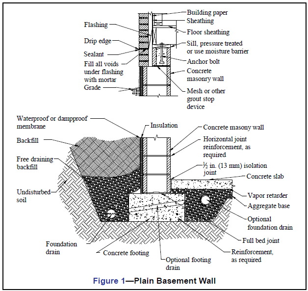
Basements are typically built as conditioned space so that they can be used for storage, work or living space. Because of this, water penetration resistance is of paramount importance to basement wall design and construction.
Following recommended backfill procedures will help prevent basement wall cracking during this operation. Walls should always be properly braced to resist backfill soil loads or have the first floor diaphragm in place prior to backfilling. Otherwise, a wall designed to be supported at the top may crack or even fail from overstressing the wall. Similarly, heavy equipment, such as bulldozers or cranes, should not be operated over the backfill during construction unless the basement walls are appropriately designed for the higher resulting loads.
The top 4 to 8 in. (102 to 203 mm) of backfill should be low permeability soil so rain water absorption into the backfill is minimized. Finished grade should be sloped away from the building.
Control joints are not typically used in foundation walls due to concerns with waterproofing the joint and the fact that shrinkage is less significant in below grade walls due to relatively constant temperature and moisture conditions. If warranted, horizontal joint reinforcement can be installed as a crack control measure.
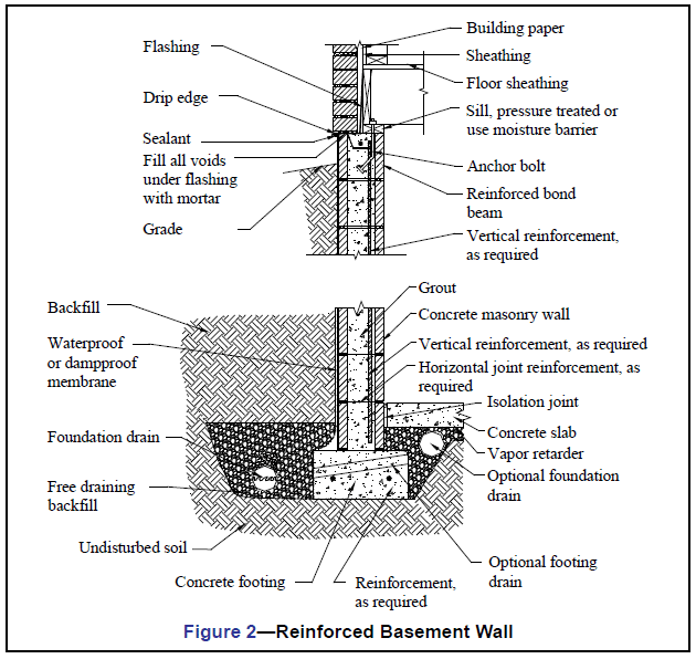
The foundation drain shown in Figures 1 and 2 can also be located on the interior side of the footing, or on both sides if necessary. The drain should be placed below the top of the footing. The optional footing drain shown, such as 2 in. (51 mm) PVC pipe at 8 ft (2400 mm) on center, allows water on the interior to reach the foundation drain. Footing drains can either be cast into the footing or constructed using plastic pipes through the bottom of the first course of masonry, directly on top of the footing.
For reinforced construction (Figure 2), reinforcing bars must be properly located to be fully functional. In most cases, vertical reinforcement is positioned towards the interior face of below grade walls to provide the greatest resistance to soil pressures.
A solid top course on the below grade concrete masonry wall spreads loads from the building above and also improves soil gas and termite resistance. Where only the top course is to be grouted, wire mesh or another equivalent grout stop material can be used to contain the grout to the top course. Note that local codes may restrict the use of foam plastic insulation below grade in areas where the hazard of termite damage is high.
STEMWALLS FOR CRAWLSPACES
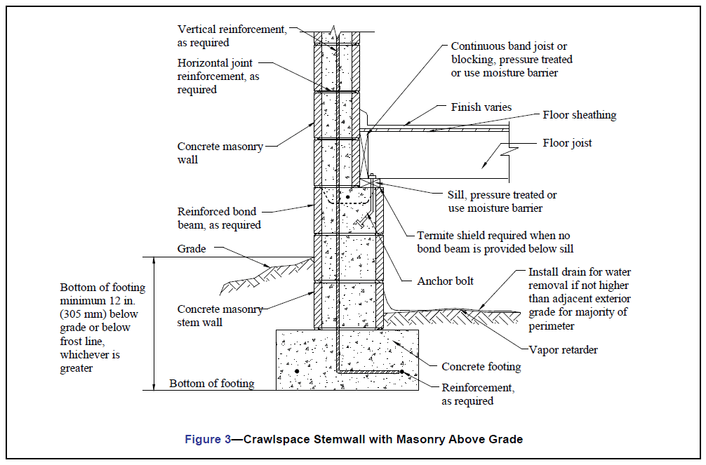
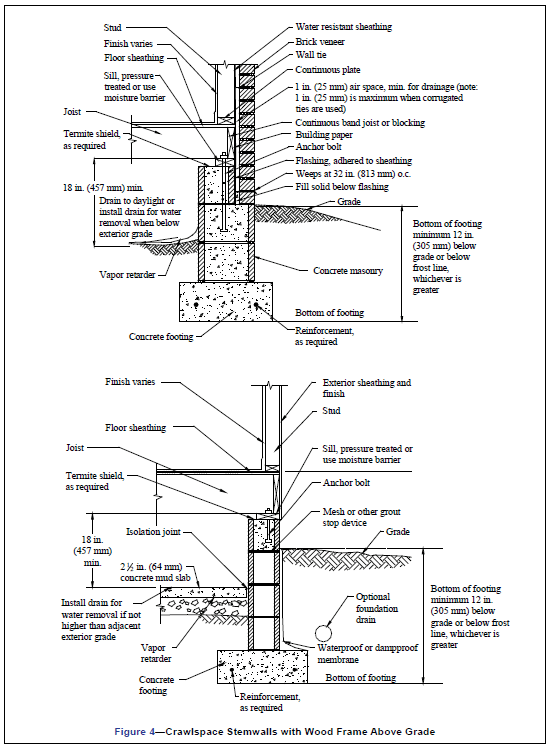
Unlike basements, crawlspaces are typically designed as unconditioned spaces, either vented or unvented. Several alternate crawlspace constructions are shown in Figures 3 and 4.
Although most building codes require operable louvered vents near each corner of a crawl space to reduce moisture buildup, research has shown that the use of a moisture retardant ground cover eliminates the need for vents in many locations (ref. 6). If the crawlspace is vented, the floor, exposed pipes and ducts are typically insulated. If unvented, either the walls or the floor above can be insulated. Unvented crawlspaces must have a floor covering to minimize moisture and, where applicable, soil gas entry. A vapor retarder (typically 6-mil (0.15 mm) polyethylene, PVC or equivalent) is good practice to minimize water migration and soil gas infiltration. A 2 1/2 in. (64 mm) concrete mud slab is generally used when a more durable surface is desired for access to utilities. A thicker concrete slab may be desirable, particularly if the crawlspace will be used for storage. A dampproof coating on the exterior crawlspace wall will also help prevent water entry into the crawlspace.
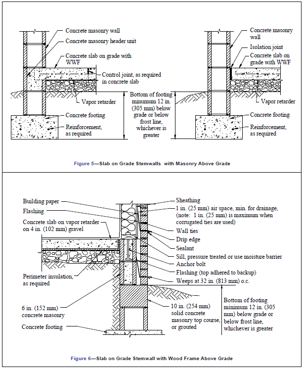
STEMWALLS FOR SLAB ON GRADE
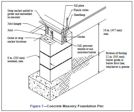
A stemwall with slab on gradesupports the wall above and often also provides a brick (ref. 7) requires a foundation pier to have a minimum nominal thickness of 8 in. (203 mm), with a nominal height not exceeding four times its nominal thickness and a nominal length not exceeding three times its nominal thickness. Note that the International Building Code, (ref. 8) allows foundation piers to have a nominal height up to ten times the nominal thickness if the pier is solidly grouted, or four times the nominal thickness if it is not solidly grouted.
REFERENCES
- Annotated Design and Construction Details for Concrete Masonry, CMU-MAN-001-03, Concrete Masonry and Hardscapes Association, 2003.
- Concrete Masonry Basement Wall Construction, TEK 03-11, Concrete Masonry and Hardscapes Association, 2001.
- Preventing Water Penetration in Below-Grade Concrete Masonry Walls, 19-03B, Concrete Masonry and Hardscapes Association, 2012.
- Basement Manual: Design and Construction using Concrete
Masonry, CMU-MAN-002-01, Concrete Masonry and Hardscapes
Association, 2001. - Building Code Requirements for Structural Concrete, ACI 318 -02.
American Concrete Institute, 2002. - 2001 ASHRAE Handbook, Fundamentals. American Society
of Heating, Refrigerating and Air-Conditioning Engineers, Inc., 2001. - Building Code Requirements for Masonry Structures, ACI 530-02/
ASCE 5-02/TMS 402-02. Reported by the Masonry Standards Joint Committee, 2002. - International Building Code. International Code Council, 2000.
- Standard Specifications for Tolerances for Concrete Construction and Materials, ACI 117-90. American Concrete Institute, 1990.