
INTRODUCTION
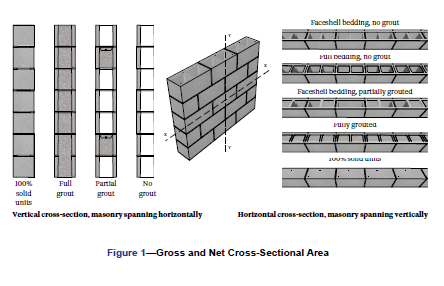
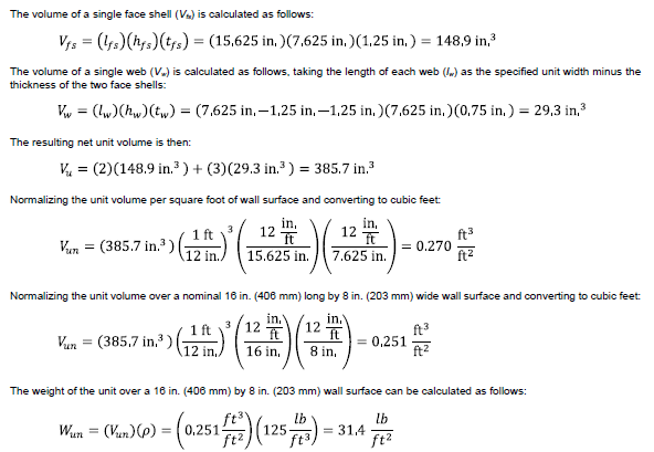
TMS 402/602-16, Building Code Requirements and Specification for Masonry Structures (REF. 1), requires that stresses in masonry assemblies resulting from design loads are based on the minimum net section properties of the member under consideration. These section properties, in turn, are based on the specified dimensions of the construction. Dead loads, which include the weight of the concrete masonry assembly, are defined by the legally adopted building code, albeit not to the detail necessary for design application. As illustrated in FIGURE 1, both assembly weights and section properties can vary due to:
- The size and configuration of the concrete masonry unit.
- Mortar bedding area, which has a small impact on weight, but a large impact on section properties. Solid units are required to be fully-bedded by TMS 402/602. Unless specified otherwise, hollow units are face shell bedded.
- Presence of grouting, both vertical and horizontal grouting, changes assembly weight and section properties.
This TEK Note discusses concrete masonry assembly weights and section properties, including calculation methodologies to determine these properties.
SOLUTIONS SUMMARY
Assembly Weights
Assembly weights are an estimate of the weight of the concrete masonry assembly. These weights may be expressed as an absolute value (e.g., lb or kN) or as a load over a normalized area (e.g., lb/ft.2 or MPa).For convenience, the normalized load is most frequently used in practice. Assembly weights are most heavily influenced by presence and spacing of grout, unit density, and unit size. In addition to factoring into the design loads of a structure, assembly weights are used to determine other assembly properties such as Sound Transmission Class (STC) ratings and heat capacity.
Section Properties
Engineered design of concrete masonry uses section properties to determine the strength, stiffness, and deflection of the assembly under consideration. Section properties may be calculated for:
- Minimum Net Cross-Sectional Properties – are based on the smallest cross-section of a member or assembly (typically a mortar joint) and are used for determining the design stresses resulting from the application of design loads.
- Average Cross-Sectional Properties – are based on a typical or average cross-section of the member or assembly and are used for determining the elastic stiffness of a member or assembly.
- Cracked or Effective Cross-Sectional Properties – are based on the cracked cross-section of a member or assembly and are used to determine the resulting inelastic stiffness and deflection under load. Because cracked or effective cross-sectional properties vary depending on the type and magnitude of load applied, they are calculated separately for each design scenario.
For vertically spanning assemblies, horizontal section properties are calculated along a horizontal axis parallel to the plane of the masonry (AXIS X-X IN FIGURE 1). For horizontally spanning assemblies, vertical section properties are calculated along a vertical axis parallel to the plane of the masonry (AXIS Y-Y IN FIGURE 1).
Spreadsheet: Section Properties and Assembly Weight Calculator
The calculation of assembly weights and section properties is not difficult, but can be time consuming. To facilitate this design step, users can refer to the Concrete Masonry Section Properties and Assembly Weight Calculator (REF. 2) to determine quickly and efficiently these attributes for various concrete masonry assemblies, unit configurations and sizes, grouting schedules, mortar bedding, and unit densities.
1.0 CONCRETE MASONRY ASSEMBLY WEIGHTS
Assembly weights are used directly to calculate:
- Sound transmission class (STC) ratings, with heavier assemblies providing higher STC ratings and hence better sound insulation. See TEK 13-01D, Sound Transmission Class Ratings for CM Walls (REF. 3), for further information.
- Heat capacity, a measurement of thermal storage capacity, increases with heavier assemblies providing higher heat capacities and potentially better energy performance. See TEK 06-16A, Heat Capacity (HC) Values for Concrete Masonry Walls (REF. 4), for further information.
- Seismic design loads, which increase as the mass of the structure increases.
- Dead loads on structural members such as lintels and foundations and used to resist uplift. and overturning for high wind resistance.
Additional assembly properties are also impacted by assembly weight, although estimates of these properties are based on concrete density or aggregate type rather than directly on assembly weight. One such property is fire resistance ratings, with lower density assemblies providing higher fire resistance ratings as reviewed in TEK 07-01D, Fire Resistance Ratings of Concrete Masonry Assemblies (REF. 5). Another property is thermal resistance, with lower density assemblies providing higher R-values and better energy performance.
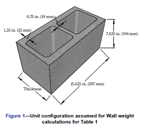
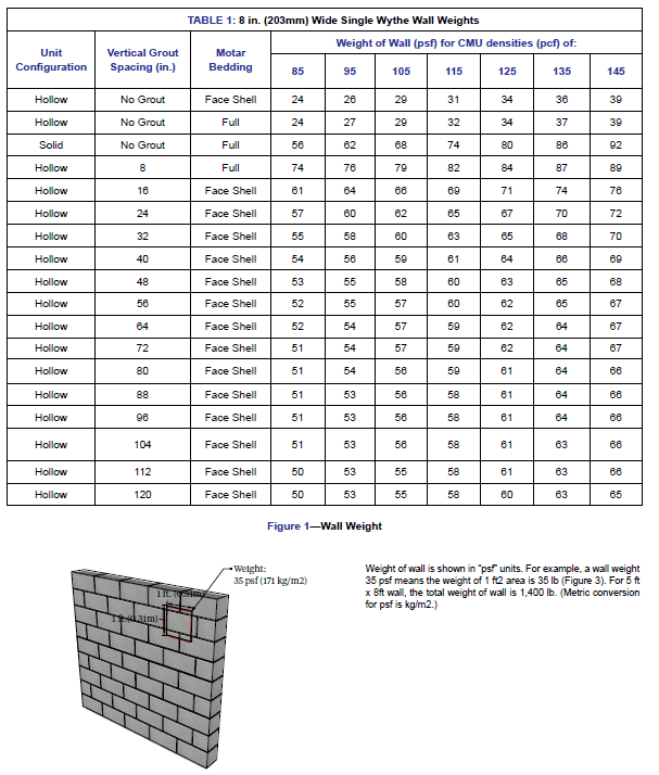
TABLE 1 summarizes typical assembly weights for an 8 in. (203 mm) wide concrete masonry unit assembly with varying unit densities and spacing of vertically grouted cells. These values are based on the following conditions:
- Minimum face shell and web thickness requirements of ASTM C90-21, Standard Specification for Loadbearing Concrete Masonry Units (REF. 6).
- All mortar joints are 3/8 in. (9.5 mm) thick. The mortar joint depth is equal to the thickness of the face shell or web on which it is placed.
- Each unit has square ends and two square cores with specified dimensions as shown in FIGURE 2.
- Mortar density is 125 lb/ft3 (2,003 kg/m3).
- Grout density is 140 lb/ft3 (2,243 kg/m�).
- Horizontal grout placement is 16 in. (406 mm) on center.
The accompanying spreadsheet, Concrete Masonry Section Properties and Assembly Weight Calculator (REF. 2), can be used to determine the weight of different concrete masonry assemblies based on user-defined inputs.
1.1 EXAMPLE PROBLEM: CALCULATING ASSEMBLY WEIGHT
Calculate the weight of a concrete masonry wall constructed of hollow concrete masonry units having nominal dimensions of 8 in. x 8 in. x 16 in. (203 mm x 203 mm x 406 mm). The spacing of vertically grouted cells is 16 in. on center and the spacing of horizontally grouted courses is 24 in. on center. The units have two 1.25 in. thick face shells and three 0.75 in. thick webs. The assembly has the following properties:
- Mortar thickness: 0.375 in.
- Mortar density: 125 lb/ft3
- Mortar bedding: Face shell bedding
- Grout density: 140 lb/ft3
- Unit density: 125 lb/ft3
- Specified unit width = 7.625 in.
- Specified unit height = 7.625 in.
- Specified unit length = 15.625 in.
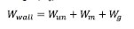
The weight of the concrete masonry wall assembly (Wwall) is the sum of masonry unit weight (Wun), mortar weight (Wm) and grout weight (Wg). It can be calculated as follows:
1.1.1 CMU Weight:
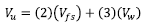
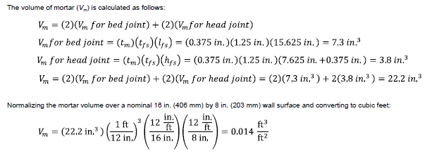
The actual volume of a concrete masonry unit can be determined using the procedures of ASTM C140 (REF. 7). Absent this information, however, the unit volume can be estimated with sufficient accuracy using the specified dimensions of the unit. In accordance with ASTM C90 (REF. 5), the minimum specified face shell and web thicknesses for an 8 in. (203 mm) nominal width unit are 1.25 in. (31.8 mm) and 0.75 in. (18.8 mm), respectively. Assuming that this unit has two cells and three fullheight webs as illustrated in FIGURE 2 the resulting unit volume (Vu ) can be calculated as follows:
1.1.2 Mortar weight:
Mortar weight (Wm) includes the weight of mortar at bed joint and head joint. In this example, face shell bedding is used for mortar, therefore the bed joint covers both the face shell area for both face shells. The head joint mortar thickness is equal to the face shell thickness. The volume of mortar (Vm) is calculated as follows:
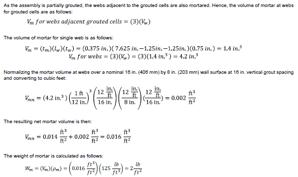
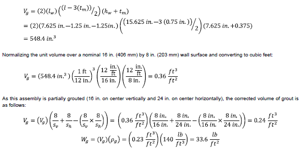
1.1.3 Grout Weight:
Calculating the volume of grout (Vg) starts with calculating the available volume in a unit that grout can be placed. This is equal to the volume of two cells in a unit. The length of each cell is the specified unit width minus the thickness of the two face shells. The width of each cell is half the specified unit length minus the total thickness of the web:
1.1.4 Assembly Weight:
The weight of wall assembly over a nominal 16 in. (406 mm) by 8 in. (203 mm) wall surface is as follows:

2.0 SECTION PROPERTIES OF CONCRETE MASONRY ASSEMBLIES
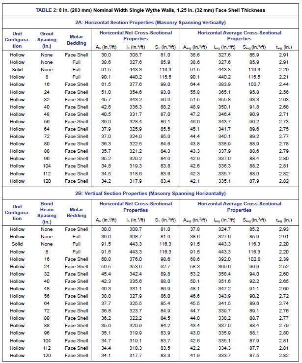
TABLE 2 summarizes typical assembly section properties for an 8 in. (203 mm) nominal width concrete masonry assembly with varying spacing of grouted cells. The net and average horizontal section properties are listed in TABLE 2A, while vertical section properties are listed in TABLE 2B. These values are based on the following conditions:
- Standard unit dimensions are based on the minimum face shell and web thickness requirements of ASTM C90-21, Standard Specification for Loadbearing Concrete Masonry Units (REF. 6).
- Each unit has square ends and two square cores with specified dimensions as shown in FIGURE 2.
- All mortar joints are 3/8 in. (9.5 mm) thick.
All mortar joints are the same depth as the thickness of the face shell or web on which they are placed.
The following section properties are presented in Table 2A and 2B:
An – net cross-sectional area
I – moment of inertia
S – section modulus
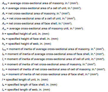
r – radius of gyration
Net section properties (An, In, and Sn) are calculated based on the minimum net cross-sectional area of an assemblage. These values are related to the critical section when determining stresses due to an applied load (REF. 8). Average section properties (Aavg, Iavg, Savg and ravg) correspond to an average cross-sectional area of an assemblage, and are used to determine stiffness or deflection due to applied loading (REF. 8).
The accompanying spreadsheet, Section Properties and Assembly Weight Calculator (REF. 2), can be used to determine the section properties of different unit sizes and configurations based on user-defined inputs.
2.1 Example Problem: Calculating Net Section Properties
Calculate the section properties of a concrete masonry assembly constructed with hollow 8 in. x 8 in. x 16 in. nominal dimension concrete masonry units. The units have two face shells that are both 1.25 in. thick and three webs that are all 1 in. thick. The assembly has a 16 in. on center vertical grout spacing and face shell mortar bedding. Calculate section properties for masonry spanning vertically. The assembly has the following additional properties:
- Specified unit width = 7.625 in.
- Specified unit height = 7.625 in.
- Specified unit length = 15.625 in.
- Mortar thickness: 0.375 in.
As the direction of span is vertical, horizontal net-section properties are calculated along a horizontal axis parallel to the plane of the masonry (AXIS X-X IN FIGURE 1).
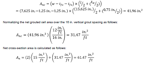
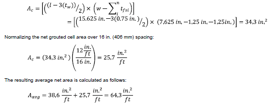
2.1.1 Net cross-sectional area:
The net cross-sectional area (An) is total of face shell area and grouted cell area. It can be calculated as:

The net grouted cell area (Anc) is calculated by multiplying the length of the cell by the width of the cell. The length of the cell is the specified unit width minus the thickness of two face shells. The width of the cell (including two webs) is half the the specified length of the unit plus half of the mortar joint thickness.
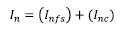
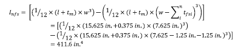
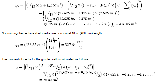
2.1.2 Net moment of inertia:
The net moment of inertia (In) is the sum of the moment of inertia for the face shells from the middle of the unit and the grouted cell (normalized for 16 in. on center spacing):
Moment of inertia of the face shell can be calculated by taking moment of inertia of the full unit minus the moment of inertia for the portion of the unit that is comprised of webs:
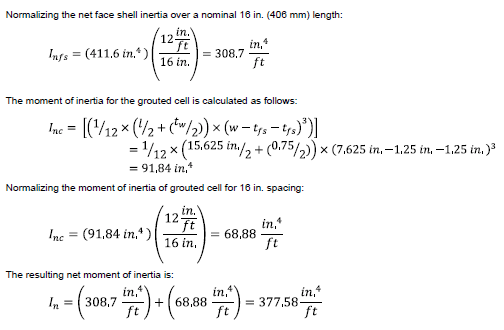
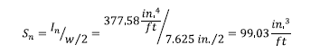
2.1.3 Net section modulus:
Net section modulus is calculated as follows:
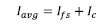
2.1.4 Average cross-sectional area:
Average cross-sectional area can be calculated taking sum of the area of unit and the area of grouted cell at 16 in. on center vertical grout spacing:
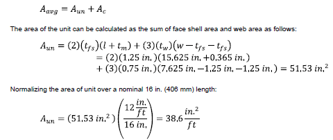
The area of the grouted cell is calculated as the product of the length and the width of the cell. The length of the cell is the specified unit width minus the thickness of two face shells. The width of the grouted cell is half the specified unit length minus the web thickness):
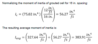
2.1.5 Average moment of inertia:
The average moment of inertia (Iavg) is the sum of the moment of inertia of the face shells from the middle of the unit plus the grouted cell for 16 in. spacing:
The moment of inertia of the face shell can be calculated taking the moment of inertia of the full unit minus the moment of inertia of web portion. For this, the width is the nominal length minus the total web thickness and the length is the width minus both face shell thicknesses:
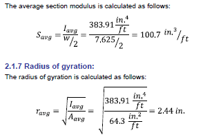
2.1.6 Average section modulus:
The average section modulus is calculated as follows:
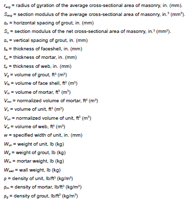
NOTATIONS
REFERENCES:
- Building Code Requirements and Specification for Masonry Structures, TMS 402/602-16, The Masonry Society, 2016, www.masonrysociety.org.
- Concrete Masonry Section Properties and Assembly Weight Calculator, CMU-XLS-003-19, Concrete Masonry and Hardscapes Association, www. masonryandhardscapes.org.
- Sound Transmission Class Ratings for CM Walls, TEK 13-01D, Concrete Masonry and Hardscapes Association, www.masonryandhardscapes.org
- Heat Capacity (HC) Values for Concrete Masonry Walls, TEK 06-16A, Concrete Masonry and Hardscapes Association, www.masonryandhardscapes.org.
- Fire Resistance Ratings of Concrete Masonry Assemblies, TEK 07-01D, Concrete Masonry and Hardscapes Association, www.masonryandhardscapes.org
- Standard Specification for Loadbearing Concrete Masonry Units, ASTM C90-21, www.astm.org.
- Standard Test Methods for Sampling and Testing Concrete Masonry Units and Related Units, ASTM C140/C140M-21, www.astm.org.
- International Building Code (IBC) (all editions), International Code Council, www.iccsage.org.
COMMONLY ASKED QUESTIONS
1.Can 4 in. (102 mm) nominal width concrete masonry units be reinforced and grouted?
While there are no code restrictions to grouting 4 in. (102 mm) concrete masonry assemblies, because of the small core size and resulting difficulty in consolidating grout, these units are rarely grouted.
2. If units are specified to have face shells or webs than are larger than the minimum requirements of ASTM C90 (for example, a semi-solid unit is specified), can these dimensions be used in determining the minimum net cross-sectional properties?
Yes, if specified dimensions are larger than the minimum requirements, those dimensions can be used to determine minimum net cross-sectional properties.
3. When specifying a concrete masonry unit by density classification (i.e., lightweight, medium weight, or normal weight units), what actual density is commonly assumed when determining the assembly weight?
Density commonly assumed for determining the assembly weight for each density classification is:
- Lightweight: 103 lb/ft3 (1,650 kg/m3)
- Medium weight: 115 lb/ft3 (1,842 kg/m3)
- Normal weight: 135 lb/ft3 (2,163 kg/m3)
4. Should the section properties for reinforced concrete masonry assemblies be based on cracked or uncracked section properties?
Section properties for reinforced concrete masonry assemblies should be based on the cracked section properties. In design of reinforced masonry, tensile resistance provided by the masonry units is neglected and it is assumed that all tensile stresses are resisted by the reinforcement. Therefore, masonry subjected to net tensile stresses is assumed to be cracked.