
INTRODUCTION
The most widely used standards for specifying concrete masonry units in the United States are published by ASTM International. These ASTM standards contain minimum material and property requirements that assure quality performance. These requirements include items such permitted constituent materials, minimum compressive strength, maximum linear drying shrinkage, maximum absorption, permissible variations in dimensions, and finish and appearance criteria.The letter and first number of an ASTM designation is the fixed designation for that standard. For example, ASTM C90 (REF. 1) is the fixed designation for loadbearing concrete masonry units. The number immediately following indicates the year of last revision (i.e., ASTM C90-16 would be the version of C90 published in 2016). Because significant changes can be introduced into subsequent editions of standards, the edition referenced by the building code or by a project specification is an important consideration when determining specific product requirements. For the discussion presented here, the ASTM requirements reviewed have remained relatively static unless otherwise noted.
SOLUTIONS SUMMARY
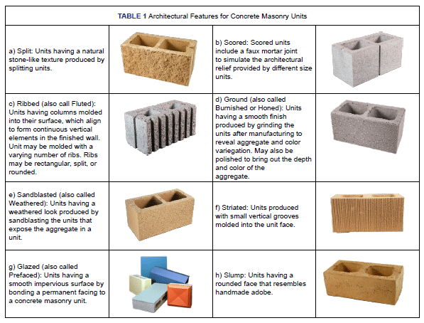
Units can be manufactured to capture a wide array of architectural features depending on project and aesthetic needs, examples of which are illustrated in TABLE 1. A single architectural feature can be combined with others to provide even greater visual appeal.
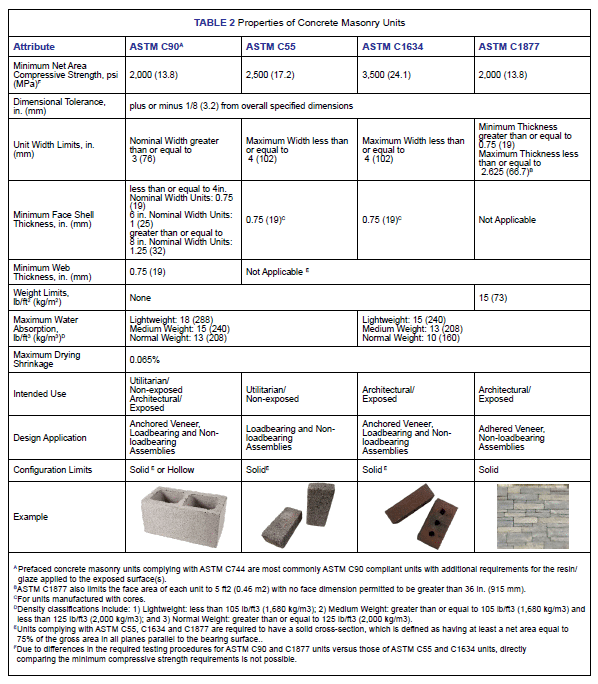
Properties for quality performance of concrete masonry units are established by ASTM specifications as summarized in TABLE 2. While there are a wide array of concrete masonry units manufactured for varying applications, the most frequently encountered specifications for dry-cast concrete masonry units include:
- ASTM C90, Standard Specification for Loadbearing Concrete Masonry Units (REF. 1)
- ASTM C55, Standard Specification for Concrete Building Brick (REF. 2)
- ASTM C1634, Standard Specfiication for Concrete Masonry Facing Brick and Other Concrete Masonry Facing Units (REF. 3)
- ASTM C744, Standard Specification for Prefaced Concrete and Calcium Silicate Masonry Units (REF. 4)
- ASTM C1877, Standard Specification for Adhered Concrete Masonry Units (REF. 5)
1.0 ASTM STANDARDS
1.1 Concrete Masonry Units – ASTM C90
ASTM C90, Standard Specification for Loadbearing Concrete Masonry Units (REF. 1), is the most commonly encountered specfication for dry-cast units. ASTM C90 units can be used in loadbearing and nonloadbearing applications, may be manufactured to be hollow or solid in cross-section, and may be reinforced as necessary to resist anticipated design loads.
Physical requirements prescribed by ASTM C90 include dimensional tolerances, minimum face shell and web thicknesses for hollow units, minimum strength and maximum absorption requirements, and maximum linear drying shrinkage (SEE TABLE 2).
Overall unit dimensions (width, height and length) can vary by no more than ± 1/8 in. (3.2 mm) from the standard specified dimensions. Exceptions include architectural features such as split-face units and faces of slump units, which are intended to provide a random surface texture. In these cases, consult local suppliers to determine achievable tolerances. Molded features such as ribs and scores must be within ± 1/16 in. (1.6 mm) of the specified dimension and within ± 1/16 in. (1.6 mm) of the specified placement on the mold.
Minimum face shell and web thicknesses are those deemed necessary to achieve satisfactory structural and nonstructural performance. In addition to minimum permissible web thicknesses for individual webs, ASTM C90 also requires a minimum normalized web contact area. When evaluating this normalized web area, the portion of a unit to be filled with grout is exempted. This provision avoids excluding units intentionally manufactured with reduced webs, including bond beam units and open-end block, where grout fulfills the structural role of the web.
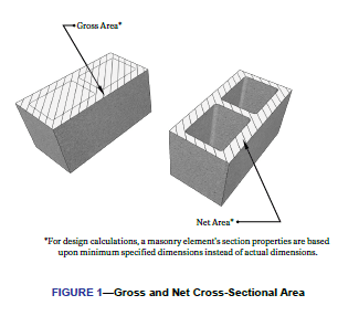
The minimum net area compressive strength of concrete masonry units complying with ASTM C90 is 2,000 psi (13.8 MPa). The area used to determine the net area compressive strength is calculated from the unit net volume based on tests described in ASTM C140/C140M, Standard Test Methods for Sampling and Testing Concrete Masonry Units and Related Units (REF. 6). Gross and net areas of a concrete masonry unit are shown in FIGURE 1.
Absorption is a measure of the total water required to fill all voids within the net volume of concrete in a unit. It is determined from the weight-per-unit-volume difference between saturated and oven-dry units. Aggregates with relatively large pores, such as some lightweight aggregate, have a greater absorption than dense, nonporous aggregates. As a result, lightweight units are permitted higher absorption values than medium or normal weight units. Maximum permissible water absorption requirements are shown in TABLE 2.
Because concrete masonry units tend to contract as they dry, ASTM C90 limits their potential drying shrinkage to 0.065%, measured using ASTM C426, Standard Test Method for Linear Drying Shrinkage of Concrete Masonry Units, (REF. 7). Limiting the maximum potential drying shrinkage mitigates the potential for cracking when combined with the crack control recommendations of CMU-TEC-009-23, Crack Control Strategies for Concrete Masonry Construction (REF. 10E), are followed.
1.2 Concrete Facing Brick and Other Concrete Masonry Facing Units – ASTM C1634
ASTM C1634, Standard Specification for Concrete Facing Brick and Other Concrete Masonry Facing Units (REF. 3) applies to concrete masonry units with the following characteristics: a maximum width of 4 in. (102 mm); a weight that will typically permit the unit to be lifted and placed using one hand; and an intended to be used where one or more unit faces will be exposed in service.
TABLE 2 includes the requirements for ASTM C1634 units for minimum compressive strength, maximum linear drying shrinkage, and maximum absorption requirements. Unless otherwise specified, concrete brick are either 100% solid or cored at the option of the manufacturer. For cored concrete building brick, the net cross-sectional area in any plane parallel to the surface containing the cores shall be at least 75% of the gross cross-sectional area measure in the same plane. No part of any core hole shall be less than 3⁄4 in. (19.1 mm) from any edge of the unit. ASTM C1634 refers to ASTM C140/C140M (REF. 6) for compression testing, which requires compression test specimens for concrete brick to have a height that is 60% +/- 10% of its least lateral dimension to minimize the impact of specimen aspect ratio on tested compressive strengths.
1.3 Concrete Building Brick – ASTM C55
A concrete building brick covered by ASTM C55 (REF. 2) is distinguished from a concrete facing brick covered by ASTM C1634 (REF. 3) primarily by its intended use; whereby a facing brick is used in exposed applications and a building brick is used in non-exposed or utilitarian applications. There are also differences in the required minimum compressive strength and maximum permitted absorption between facing brick and building brick as summarized in TABLE 2.
1.4 Prefaced Concrete Masonry Units – ASTM C744
ASTM C744, Standard Specification for Prefaced Concrete and Calcium Silicate Masonry Units (REF. 4) establishes requirements for the facing materials applied to masonry unit surfaces. For the units onto which the surface is molded, ASTM C744 requires compliance with the requirements contained in ASTM C55, ASTM C90 or ASTM C129, with units complying with ASTM C90 being the most frequently used. Facing requirements in ASTM C744 include resistance to crazing, surface burning characteristics, adhesion, color permanence, chemical resistance, cleansability, abrasion, and dimensional tolerances. Because of these surface characteristics, prefaced concrete masonry units make an ideal choice for use in kitchens, bathrooms, and similar locations where frequent cleaning is necessary.
1.5 Adhered Concrete Masonry Units – ASTM C1877
ASTM C1877, Standard Specification for adhered Concrete Masonry Units, (REF. 5) provides minimum requirements for dry-cast concrete masonry units used in adhered veneer applications. Physical requirements for these units are listed in TABLE 2.
2.0 FINISH AND APPEARANCE
Because concrete masonry often provides the final exposed surface of the finished construction, the resulting appearance and aesthetics are influenced by:
- The design and detailing, specifically the attention to modular coordination and layout;
- The quality of the units and mortar; and
- The quality of workmanship during installation.
Each ASTM standard for concrete masonry units addresses unit aesthetics, although these requirements vary depending upon the intended application of the unit. At a minimum, all concrete masonry units are required to be sound and free of cracks or other defects that interfere with the proper placement of the unit or significantly impairs the strength or permanence of the construction. Given the practical logistics of producing, handling, and transporting units to a jobsite, ASTM does permit up to 5% of a shipment of units to exhibit the following:
- Units that do not meet the overall dimensional tolerances for width, height, and length;
- Units with finished face(s) containing chips larger than 1 in. (25.4 mm) in any direction;
- Units with finished face(s) containing cracks wider than 0.02 in. (0.5 mm) and longer than 25% of the nominal height of the unit;
- Units that are broken; and
- Units that show objectionable imperfections. This is based on viewing the unit face(s) from a distance of at least 20 ft. (6.1 m) under diffused lighting. (Note that ASTM defines ‘finished face’ as any surface(s) of a manufactured masonry unit intended by the manufacturer to be exposed to view.)
As concrete masonry units are manufactured from natural materials, no two units have the exact same appearance. For units intended to be exposed in service, inclusive of units complying with ASTM C90, ASTM C1634, and ASTM C1877, these specifications require that the color and texture of the units be approved based on a sample consisting of not less than four units representing the range of texture and color permitted.
As units may become soiled or damaged during or immediately following installation, the use of a sample panel in accordance with TMS 602, Specification for Masonry Structures (REF. 8), and as summarized in TEK 03-08A, Concrete Masonry Construction (REF. 10D), is critical for establishing a baseline for comparing the finished work. Sample panels capture the range of unit and mortar properties, installation of accessory materials such as flashing and caulking, workmanship, cleaning procedures, and the application of any post-applied coatings or sealants. When assessing the acceptable level of the finished work, visual assessment of the sample panel or finished construction should follow the same baseline as established by ASTM for individual units by viewing the construction from a distance of at least 20 ft. (6.1 m) under diffused lighting for the presence of objectionable imperfections.
3.0 SIZES AND SHAPES OF CONCRETE MASONRY UNITS
Concrete masonry units are manufactured in different sizes, shapes, colors, and textures to achieve a number of finishes and functions. Certain concrete masonry sizes and shapes are considered standard, while others are popular only in certain regions. Local manufacturers can provide detailed information on specific products and the feasibility of producing custom units.
3.1 Unit Sizes
3.1.1 ASTM C90 Unit Sizes
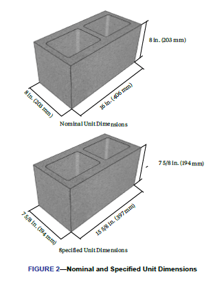
Typically, concrete masonry units have nominal face dimensions of 8 in. (203 mm) high by 16 in. (406 mm) long, although other nominal face dimensions are available that accommodate an 8 in. (203 mm) module. These include units with nominal heights of 4 in. (102 mm) and nominal lengths of 24 in. (610 mm) to 32 in. (813 mm) to provide varying architectural relief or construction productivity. Nominal thicknesses include 4, 6, 8,10, 12, 14, and 16 in. (102, 152, 203, 254, 305, 356, and 406 mm).
Nominal dimensions refer to the module size for planning bond patterns and modular layout with respect to door and window openings. Specified dimensions of concrete masonry units are typically 3/8 in. (9.5 mm) less than nominal dimensions, so that a 4 or 8 in. (102 or 203 mm) module is maintained with 3/8 in. (9.5 mm) mortar joints. FIGURE 2 illustrates nominal and specified dimensions for a nominal 8 x 8 x 16 in. (203 x 203 x 406 mm) concrete masonry unit.
3.1.2 ASTM C55 and ASTM C1634 Unit Sizes
Concrete brick complying with ASTM C55 (REF. 2), or ASTM C1634 (REF. 3), are available in a wide array of nominal lengths and heights; typically with a nominal 4 in. (102 mm) width. Standard dimensions of concrete brick are the manufacturer’s designated dimensions. Nominal dimensions of modular size concrete building brick are equal to the standard dimensions plus the thickness of one mortar joint. Nominal dimensions of non-modular size concrete building brick usually exceed the standard dimensions by 1⁄8 to 1⁄4 in. (3.2 to 6.4 mm). Concrete brick may be 100% solid or cored. For cored concrete building brick, the net cross-sectional area in any plane parallel to the surface containing the cores is not permitted to exceed 25% of the gross cross-sectional area measured in the same plane.
3.1.3 ASTM C1877 Unit Sizes
Adhered concrete masonry units complying with ASTM C1877 (REF. 5) are used solely in nonstructural applications where the units are adhered to their structural backing. These units are manufactured to simulate conventional CMU, clay masonry, concrete brick, and stone and as such exhibit a wide and sometime random array of shapes and sizes. As such, specified dimensions of concrete building brick are the manufacturer’s designated dimensions. ASTM does, however, place limits on the minimum and maximum thickness of adhered concrete masonry units as well as dimensional limits on the surface as summarized in TABLE 2.
3.2 Unit Configuration Options
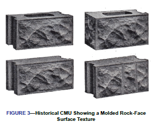
The shape of concrete masonry units has changed considerably since the early days of production late in the 19th century (FIGURE 3). This evolution in configuration continues today for aesthetic, production, functional, or performance reasons with more contemporary unit configurations illustrated in FIGURE 4. Given the long history of concrete masonry and masonry construction in general, regional differences in unit terminology have developed whereby a unit may be referred to by one name in one region and by another elsewhere. These differences in semantics have no impact on the properties or performance of the units.
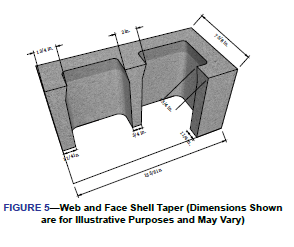
One feature common to all hollow concrete masonry units manufactured today is the presence of tapered face shells and webs. This taper, or draft, in the unit facilitates stripping of the units from their mold during production. Units may be produced with a straight taper from the top to the bottom of the unit, tapered with a flare, or some combination of these two configuration options as shown in FIGURE 5. This small change in a unit’s configuration does not impact the structural properties of the unit as design is required to be based on the minimum specified unit dimensions, but does create a slightly larger surface area on the top of the unit when installed to facilitate handling and spreading mortar on the units.
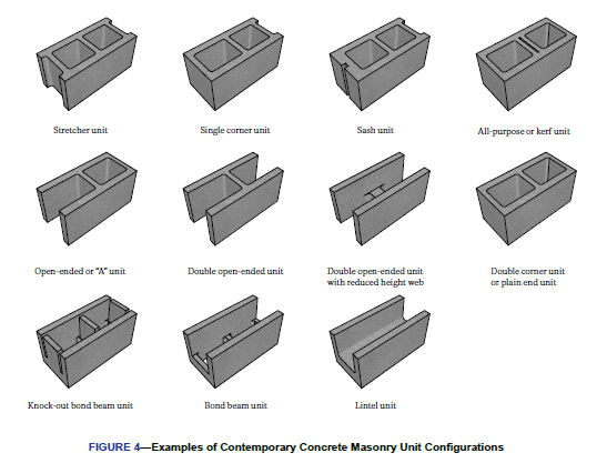
Although there are regional variations and countless unique, specialized, and proprietary unit configurations in use today, the most commonly produced configuration for hollow, loadbearing concrete masonry units is a two-cell, three-web unit similar to that shown in FIGURE 5. Local market conditions and preferences will continue to drive specific nuances of unit configuration options illustrated in FIGURE 4. Prior to specifying a specific unit configuration, local manufacturers should be consulted for unit availability.
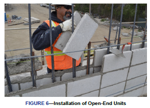
Examples of regionally available unit configurations include open-end units whereby units are produced without one or both end webs as shown in FIGURE 4. Open-end units allow the units to be threaded around reinforcing bars as shown in FIGURE 6, thus eliminating the need to lift units over the top of previously installed reinforcing bars during construction. In addition to being lighter, open-end units provide for a larger cell, which reduces congestion in highly reinforced assemblies. Note that double open-end units effectively require the assembly to be solid grouted as there is no means of confining grout to isolated vertical cells.
Horizontally reinforced bond beams in concrete masonry assemblies can be constructed either by saw cutting a portion of the webs out of a standard unit or by using bond beam units. Bond beam units are manufactured either with reduced webs or with “knock-out” webs, which are removed prior to unit placement in the wall. Lintel units are similar to bond beam units except the bottom of the unit is solid to confine grout to the lintel.
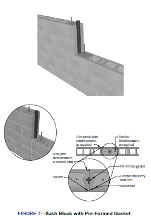
Sash block have a vertical groove molded into one end to accommodate a window or door sash. Two sash block can also be laid with the grooves adjacent to one another to accommodate a preformed control joint gasket as shown in FIGURE 7. An all- purpose or kerf unit contains two closely spaced webs in the center, rather than the typical single web. This allows the unit to be easily split on the jobsite, producing two half-length units for use at openings or at the ends or corners of a wall.
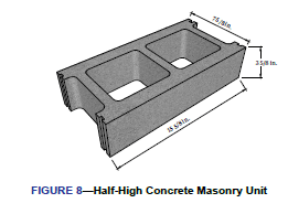
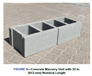
Some units are produced to varying nominal heights (FIGURE 8) and nominal lengths (FIGURE 9) to provide a different
architectural relief to the finished assembly or to increase construction productivity. These units can also be produced with scores or dummy joints as shown in FIGURE 9 to alter the perceived scale of the units. With large format units, however, mechanical or other assisted lifting devices may be necessary.
3.3 Screen Block
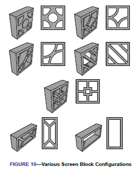
Not all concrete masonry units are used as part of a building enclosure. Screen walls are used in both interior and exterior applications to divide space, provide privacy, buffer wind, and provide diffused shade. Because screen walls are used predominately in nonloadbearing applications, the variety of unit shapes and sides is nearly limitless as illustrated in FIGURE 10. For more information on screen block design and construction, refer to TEK 03-16A, Concrete Masonry Screen Walls (REF. 10F).
4.0 UNIT CONFIGURATION DESIGN IMPLICATIONS
In some cases, a unit’s configuration is driven by the need to facilitate or increase production, transportation, or construction efficiency. In others, there are specific design related objectives to a unit’s configuration. The configuration of such units provides designers and contractors with the flexibility to meet more demanding requirements and performance expectations in contemporary construction.
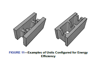
4.1 Energy Efficiency
Some unit configurations are specifically designed to increase the energy efficiency of the finished assembly. These units, FIGURE 11, typically have reduced web areas to reduce heat flow through the webs or to accommodate integral insulation. Web areas can be reduced by reducing the web height or thickness, reducing the number of webs, or both. In addition, the interior face shell of the unit can be made thicker than a typical face shell for increased thermal storage, and hence further increase energy efficiency.
For masonry units with alternate web configurations, the most significant impact on thermal performance is on the wall’s R-value. Because the webs provide a direct heat transfer path through a masonry unit, changing the size of the webs can have a significant impact on the resulting thermal properties of an unfinished single wythe assembly. Unless the resulting assembly is to be solid grouted, in which case the web configuration is irrelevant to the thermal efficiency, the effect is simple: smaller
webs result in higher R-values. This effect is most prominent with integrally insulated single wythe walls. In wall assemblies with continuous insulation (such as cavity walls), web configuration has little impact on the overall assembly R-value.
As part of a building’s exterior envelope, single-wythe concrete masonry construction serves the dual role of providing both enclosure and structural strength. As such, these assemblies usually contain reinforcement and grout. While the reinforced cells of an assembly increase the strength of the system, the grout provides a larger area for heat flow, creating a larger ‘thermal short’ within the assembly. The net result is a decrease in the steady state R-values of an assembly as the percentage of grout increases. The numerical impact of grouting on R-value varies directly with the amount of grout in the wall. For more information on concrete masonry assembly R-values and U-factors, see TEK 06-01C, R-Values of Multi-Wythe Concrete Masonry Walls and TEK 06-02C, R-Values and U-Values for Single Wythe Concrete Masonry Walls, (REF. 10C AND 10I).
4.2 Sustainability
ASTM C90 (REF. 1) was revised in 2011 to accommodate unit configurations other than the conventional two cell, three web concrete masonry unit. This allows producers to optimize unit configurations not just for energy efficiency, but also for material use. Using less material in production reduces: the demand on resources; the energy necessary to manufacture products; and the fuel required to transport units to job sites—while maintaining the high durability, low impact solution inherent in concrete masonry.
4.3 Structural Design
All concrete masonry units meeting the requirements of ASTM C90 (REF. 1) are structurally designed in the same manner, even when their configuration varies. For example, a concrete masonry unit with a nominal height of 8 in. (203 mm) is analyzed the same as a unit with a nominal height of 4 in. (102 mm). There may however, be some detailing and layout issues to consider, such as vertical coursing to maintain modularity with units of different nominal heights. Designers should understand the assumptions and conditions that may need to be considered when specifying a unit of a given configuration.
Structural design of concrete masonry assemblies is governed by the TMS 402, Building Code Requirements for Masonry Structures (REF. 8). This standard requires that an assembly’s section properties be calculated based on the minimum net cross-sectional area of an assemblage, which typically precludes the web area. Hence, net section properties are not affected by differences in web configuration. Conversely, average section properties correspond to an average cross-sectional area of an assemblage, so these values may change with differences in web configuration. Average section properties are used to determine stiffness or deflection due to an applied load. See TEK 100-02, Weights and Section Properties of Concrete Masonry Assemblies, (REF. 10H) for further information.
4.4 Fire Resistance
In practice, the fire resistance of concrete masonry assemblies is most commonly determined using the equivalent thickness method detailed in ACI/TMS 216.1-14 (19), Code Requirements for Determining Fire Resistance of Concrete and Masonry Construction Assemblies (REF. 9), the requirements of which are summarized in TEK 07-01D, Fire Resistance Ratings of Concrete Masonry Assemblies (REF. 10A). As the equivalent
thickness of a concrete masonry unit is directly related to the volume of material used in its production, some unit configurations exhibit higher fire resistance ratings than others, even when the overall nominal dimensions are the same. Note that the results of concrete masonry assemblies evaluated under a listing service (such as UL or FM Global) are only applicable to the configuration of the unit tested and cannot be extrapolated to alternative unit configurations. As with specifying any fire resistance rating for a concrete masonry assembly, these variables need to be taken into consideration during design and procurement.
4.5 Sound Abatement
TMS 302-18, Standard Method for Determining the Sound Transmission Ratings for Masonry Assemblies (REF.11), as summarized in TEK 13-01D, Sound Transmission Class Ratings for CM Walls (REF. 11B), outlines procedures for determining the Sound Transmission Class (STC) rating of concrete masonry assemblies as a function of the installed weight of the wall. For assemblies where the cells are left unfilled or partially filled with an approved material (grout or aggregate), a reduction in the equivalent thickness would reduce the installed weight of the assembly. As with fire resistance ratings, this should be accounted for when sound transmission is a consideration.
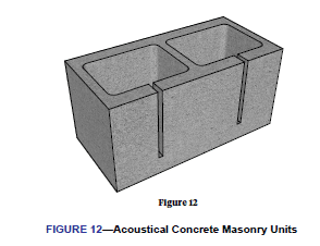
While one of the inherent physical properties of concrete masonry is its ability to decrease sound levels from one side of the assembly to the other, using units with acoustical slots such as those shown in FIGURE 12, the noise levels within an interior space can be reduced even further. Acoustical units are often used in schools, manufacturing facilities, and similar applications where improved internal acoustics are desired. A fibrous media is often placed within the cells of these units to further reduce airborne sound.
5.0 DENSITY-RELATED PROPERTIES OF CONCRETE MASONRY ASSEMBLIES
The density of a concrete masonry unit is expressed as the oven-dry density of concrete in pounds per cubic foot (lb/ft3 [kg/ m3]) as determined in accordance with ASTM C140/C140M (REF. 6). In production, the density of a given concrete masonry unit is controlled in part by the methods used to manufacture the unit, but largely by the type of aggregate used in production. By using lightweight aggregates, normal weight aggregates, or blends of lightweight and normal weight aggregates, the resulting density of concrete masonry units can be varied to achieve one or more desired physical properties.
ASTM standards for manufactured concrete masonry units define three density classes for concrete masonry units:
- Lightweight: less than 105 lb/ft3 (1,680 kg/m3);
- Medium Weight: greater than or equal to 105 lb/ft3 (1,680 kg/m3) and less than 125 lb/ft3 (2,000 kg/m3); and
- Normal Weight: greater than or equal to 125 lb/ft3 (2,000 kg/m3).
When a specific density classification or density range is desired for a project, it should be specified in the project documents along with the other physical properties of the concrete masonry units such as size, strength, color, and architectural finish. Before specifying a specific density range, designers are encouraged to first consult with manufacturers local to the project for product availability. As with all physical properties of concrete masonry, minor variation in density from unit to unit and from batch to batch should be expected.
This section reviews the various physical and design properties influenced by the density of concrete masonry units and provides references to guide the user towards a fuller discussion and more detailed information. Although most of the following discussion use lightweight and normal weight concrete masonry as examples, the properties of medium weight masonry can typically be expected to fall between the two.
5.1 Fire Resistance
Fire resistance ratings of one to four hours can be achieved with concrete masonry of various widths (thicknesses), configurations, and densities. As outlined in TEK 07-01D, Fire Resistance Ratings of Concrete Masonry Assemblies (REF. 10A), the fire resistance rating of a concrete masonry assembly can be determined by physical testing, through a listing service, or by a standardized calculation procedure. Whether through direct measurement or by calculation, the fire resistance rating of a given concrete masonry assembly varies directly with the aggregate type and with the volume of concrete in the unit, expressed as the equivalent thickness. Generally, as the density of a concrete masonry unit decreases, the fire resistance rating increases.
5.2 Sound Control
All other design variables being equal, the Sound Transmission Class (STC) value of masonry construction increases with increasing unit density. In addition to the STC rating, the value of the Noise Reduction Coefficient (NRC) can also be influenced to some extent by concrete unit density. NRC values for concrete masonry walls are tabulated according to the application of any coatings to the wall, the surface texture (coarse, medium or fine) and the density classification (lightweight or normal weight).
Assuming a similar surface texture and coating, a concrete masonry wall constructed with lightweight units will have a higher NRC than a companion wall constructed with normal weight units, due to the larger pore structure often associated with lower density units. Painting or coating the surface of the concrete masonry assembly reduces the NRC for both lightweight and normal weight concrete masonry. See TEK 13- 02A, Noise Control with Concrete Masonry (REF. 10G) for a full discussion.
5.3 Water Penetration and Absorption
Concrete masonry unit specifications establish upper limits on the amount of water permitted to be absorbed (TABLE 2). Absorption is expressed in pounds of water per cubic foot of concrete, lb/ft3 (kilograms of water per cubic meter of concrete, kg/m3). These limits vary with the density classification of the unit as shown in TABLE 2.
While the absorption values are not directly related to unit physical properties such as compressive strength and resistance to mechanisms of deterioration such as freeze-thaw, they do provide a measurement of the void structure within the concrete matrix of the unit. Several production variables can affect the void structure, including degree of compaction, water content of the plastic mix, and aggregate gradation. Due to the vesicular structure of lower density units, there is a potential for higher measured absorption than is typical for higher density units. Consequently, ASTM permits lower density units to have a higher maximum absorption value.
The higher absorption limits permitted by ASTM for lower density units do not necessarily correlate to changes in water penetration resistance. One reason is that water penetration resistance is highly affected by workmanship and dependent on detailing for water management. It is generally recognized that these two factors more heavily influence an assembly’s water penetration resistance than do other factors, such as unit density.
5.4 Aesthetic Considerations
In general, the many options available for architectural concrete masonry units can be offered in any of the three unit density classifications. However, with respect to unit appearance, any change in aggregates (whether a change in source or a change in aggregate type) used to manufacture a concrete masonry unit may change its color or texture, particularly for units with mechanically altered features such as split or ground- face surfaces. As a result, when aesthetics are an important consideration, sample units submitted for conceptual design should incorporate the specific aggregate intended to be used in the actual production of the units.
5.5 Energy Efficiency
Increasing the unit density, unit thickness, unit solid content, and amount/extent of grout, increases the installed weight of the masonry assembly, which is directly related to its heat capacity (REF. 10C). Conversely, increasing the density or amount of grout used in a concrete masonry assembly decreases its R-value. Because of the multitude of variables that determine the overall energy efficiency of a structure, some projects benefit more by increasing the thermal mass of an assembly while others see more energy efficiency by increasing the R-value. As such, the unique requirements of each project should be considered individually for maximum benefit when selecting a unit density.
5.6 Structural Design Influences
Regardless of unit density, all concrete masonry units must meet the minimum compressive strength requirements stipulated by their respective ASTM specification. It is possible to produce concrete masonry units that meet or exceed the minimum ASTM strength in any density classification, although not all combinations of physical properties may be commonly available in all regions. Therefore, local producers should always be consulted for product availability before specifying. In general, for a given concrete masonry unit mix design, higher compressive strengths can be achieved by increasing the unit density through adjustments to the manufacturing methods.
The structural design of masonry is based on the specified compressive strength of masonry, f’m, which is a function of the compressive strength of the unit and the type of mortar used in the construction, not the unit density. As such, the design flexural, shear, and bearing strengths of masonry, some deformational properties such as elastic modulus, and the structural behavior of the masonry assembly determined by codes and standards are independent of the density of the concrete masonry unit.
Unit density, however, can influence other structural design considerations, aside from compressive strength. Reducing the density of a concrete masonry unit can reduce the overall weight of a structure, and potentially reduce the required size of the supporting foundation or other structural elements. Reducing the weight of a structure or element also reduces the seismic load a structure or element must be designed to resist, because the magnitude of seismic loading is a direct function of construction material weight.
As with thermal mass and sound control, there may be circumstances where increasing the unit density is structurally beneficial. For example, the structural stability against overturning and uplift due to wind loads is increased with increasing structural weight. Hence, while increased structural weight increases seismic design forces, it also concurrently helps to resist wind loads. Therefore, there may be some structural advantage to using lightweight units in areas of high seismic risk; and normal weight units in areas prone to high winds, hurricanes and/or tornadoes. Structural design considerations, however, are often relatively minor compared to other factors that may influence the choice of unit density.
5.7 Productivity
For a given unit configuration, and with all other factors affecting production being equal, lower unit weights typically enable a mason to lay more units within a given timeframe as discussed in TEK 03-08A, Concrete Masonry Construction (REF. 10D). The resulting weight of a given unit, however, is influenced by both the unit density as well as the overall volume of material used in the production of the unit. Hence, it is possible to have a lightweight 12 in. (305 mm) unit that weighs less than a normal weight 8 in. (203 mm) unit.
5.8 Movement Control
Industry guidelines (REF. 10E) for crack control and accommodating movement within a concrete masonry structure were developed to be equally applicable to both lightweight and normal weight concrete masonry units.
6.0 ARCHITECTURAL CONCRETE MASONRY UNITS
One of the most significant architectural benefits of designing with concrete masonry is its versatility – the finished appearance of a concrete masonry wall can be varied with the unit size and shape, color of units and mortar, bond pattern, and surface finish of the units. Some of the surfaces are molded into the units during the manufacturing process, while others are applied separately. The term “architectural concrete masonry units” typically is used to describe units displaying any one of several surface finishes that affects the texture or appearance of the unit whether used in a loadbearing assembly or as a veneer.
Architectural concrete masonry units are used for interior and exterior walls, partitions, terrace walls, and other enclosures. Some units are available with the same treatment or pattern on both faces, to serve as both exterior and interior finish, thereby increasing both the economic and aesthetic advantages. Architectural units comply with the same quality standards as non-architectural concrete masonry units as summarized in TABLE 2.
Architectural concrete masonry units are often integrally colored to enhance the appearance or achieve a particular effect. Concrete masonry units are colored by adding mineral oxide pigments to the concrete mix. Mortars can also be integrally colored to blend or contrast with the masonry units.
The final unit color varies with the amount of water used in the mix (a wetter mix will generally produce lighter and brighter colors) as well as the color of the constituent materials, most notably the cement and aggregate. Both white and gray cements are available, where the use of white cement results in more vibrant colors, but also increases cost. Because of these varying factors, there are typically some subtle variations in color among units. When units must be exactly the same color to achieve a particular architectural effect, uncolored units should be used, then painted or stained the desired color.
Variegated units provide color variations within each unit, producing a marbled effect. These units are manufactured by mixing two or more different concrete colors into the same unit mold.
The units described herein and summarized in TABLE 1 are some of the more common architectural concrete masonry units. However, manufacturers may carry additional products not listed, and conversely, not all products listed will be available in all locations. Consult a local manufacturer for final unit selection.
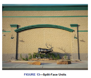
6.1 Split-Face Units
Split-face units have a natural stone-like texture produced by molding two units face-to-face, then mechanically splitting them apart after curing, creating a fractured surface as shown in FIGURE 13. Because coarse aggregate may be fractured and exposed in this process, aggregate selection can alter the final appearance. Split-faced units can also be manufactured with ribs or scores to provide strong vertical lines in the finished wall.
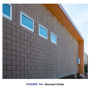
6.2 Scored Units
Scored concrete masonry units are manufactured with one or more vertical scores on the face to simulate additional mortar joints in the wall (FIGURE 14). Scored units reduce the perceived scale of the masonry while still allowing construction using full sized units. Units with one vertical score are most common, and give the appearance of 8 in. x 8 in. (203 x 203 mm) units laid in stack bond. Units may also be available with 2, 3, 5, or 7 vertical scores.
It is usually desirable to lay units so that scores align vertically. This may require different bond patterns, depending on the configuration of the scores. For example, units with two and five scores can be placed in either stack bond or in a one-third running bond to align scores in adjacent courses.
6.3 Ribbed Units
Ribbed concrete masonry units (also called fluted units) typically have 4, 6, or 8 vertical ribs molded into the units during manufacturing, which align to form continuous vertical elements in the finished wall (SEE FIGURE 15). The ribs may have either a rectangular or a circular profile, and may be either smooth or split for added texture.
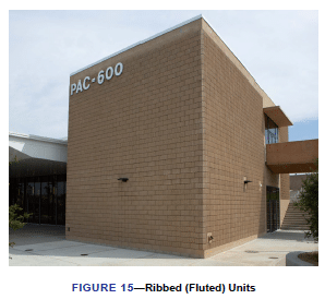
The ribs can be manufactured to project beyond the overall unit thickness (i.e., the unit thickness including ribs is thicker than a typical CMU), or with the rib projection included in the overall unit thickness. In the first case, the net area, and corresponding section properties, will be larger than those published for non-ribbed units, although the effect of this increase is typically neglected in structural calculations. In the second case, where the rib projection is included in the overall unit thickness, the designer should be aware that the actual bearing area, section modulus, and moment of inertia may be less than those published for non-ribbed units. As with scored units, the configuration of the ribs may influence the choice of bond pattern.
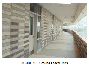
6.4 Ground Face Units (Burnished, Honed)
Ground face concrete masonry units are polished after manufacture to achieve a smooth finish, which reveals the natural aggregate colors (FIGURE 16) simulating natural stone. The finished look of the ground surface can be altered by changing aggregate type and proportions. Often, specific aggregates will be used to enhance the appearance of the polished surface, while coatings are sometimes used to deepen the color.
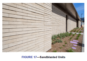
6.5 Sandblasted Units
Sand (or abrasive) blasting is used to expose the aggregate in a concrete masonry unit and results in a “weathered” look (FIGURE 17).
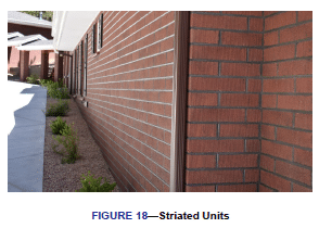
6.6 Striated (Raked) Units
Striated units achieve an overall texture by means of small vertical grooves molded into the unit face (SEE FIGURE 18). The striations are most often random, to achieve a naturally rough look, but are sometimes available in uniform striation patterns.
6.7 Glazed (Prefaced) Units
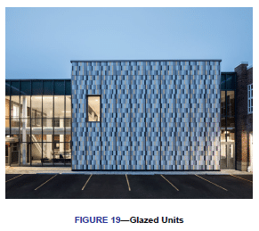
Glazed concrete masonry units are manufactured by bonding a permanent colored facing (typically composed of polyester resins, silica sand and various other chemicals) to a concrete masonry unit, providing a smooth impervious surface (FIGURE 19). Glazed units are available in a variety of vibrant colors, pastels, earth tones, and even faux granite and marble patterns. The glazed facings must comply with ASTM C744 (REF. 4), Standard Specification for Prefaced Concrete and Calcium Silicate Masonry Units, which contains minimum requirements for facing quality and dimensional tolerances. In addition, the unit to which the facing is applied must comply with ASTM C90 (REF. 1). The glazed surface is waterproof, resistant to staining and graffiti, highly impact resistant, as well as being resistant to many chemicals and bacteria.
6.8 Slump Block Units
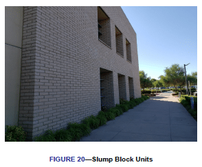
Slump block concrete masonry units have a rounded face that resembles handmade adobe (SEE FIGURE 20). They are more commonly available in the Southwest United States where adobe is part of the architectural heritage. Slump unit widths may vary as much as 1 in. (25 mm). While this variation adds to the aesthetic appeal of slump block, it may require special consideration during design, detailing, and construction.
6.9 Screen Block
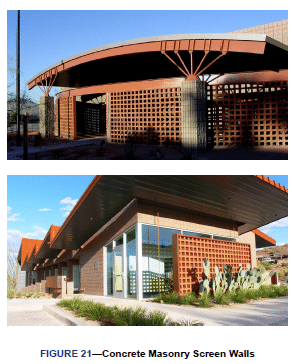
Created originally as a functional building element, the screen wall (FIGURE 21) combines privacy with observation, interior light with shade and solar heat reduction, and airy comfort with wind control for both interior and exterior applications. Curtain walls, fences, sun screens, and room dividers are just a few of the limitless applications for a concrete masonry screen wall. Due to the virtually limitless number of shapes and sizes for concrete masonry screen wall units, designers are encouraged to check on the availability of any specific shape during the early planning stages of a project.
REFERENCES
- Standard Specification for Loadbearing Concrete Masonry Units, ASTM C90 (all recent editions), www.astm.org.
- Standard Specification for Concrete Building Brick and Other Concrete Masonry Facing Units, ASTM C55 (all recent editions), www.astm.org.
- Standard Specification for Concrete Facing Brick, ASTM C1634 (all recent editions), www.astm.org.
- Standard Specification for Prefaced Concrete and Calcium Silicate Masonry Units, ASTM C744 (all recent editions), www.astm.org.
- Standard Specification for Adhered Concrete Masonry Units, ASTM C1877 (all recent editions), www.astm.org.
- Standard Test Methods for Sampling and Testing Concrete Masonry Units and Related Units, ASTM C140/C140M (all recent editions), www.astm.org.
- Standard Test Method for Linear Drying Shrinkage of Concrete Masonry Units, ASTM C426 (all recent editions), www.astm.org.
- Building Code Requirements and Specification for Masonry Structures, TMS 402/602-16, www. masonrysociety.org
- Code Requirements for Determining Fire Resistance of Concrete and Masonry Construction Assemblies, ACI/TMS 216.1-14 (19), American Concrete Institute, 2019, www. concrete.org.
- 10 TEK, Concrete Masonry and Hardscapes Association, www.masonryandhardscapes.org
- TEK 07-01D, Fire Resistance Ratings of Concrete Masonry Assemblies.
- TEK 13-01D, Sound Transmission Class Ratings for CM Walls.
- TEK 06-01C, R-Values of Multi-Wythe Concrete Masonry Walls.
- TEK 03-08A, Concrete Masonry Construction.
- CMU-TEC-009-23, Crack Control Strategies for Concrete Masonry Construction.
- TEK 03-16A, Concrete Masonry Screen Walls.
- TEK 13-01D, Noise Control with Concrete Masonry.
- TEK 100-02, Weights and Section Properties of Concrete Masonry Assemblies.
- TEK 06-02C, R-Values and U-Values for Single Wythe Concrete Masonry Walls.
- Standard Method for Determining Sound Transmission Ratings for Masonry Assemblies, TMS 302-18, The Masonry Society, 2018, www.masonrysociety.org.
- FAQ, Concrete Masonry and Hardscapes Association, www.masonryandhardscapes.org.
- CMU-FAQ-014-14, What is the Difference Between a “Cinder Block” and a “Concrete Block”?